
 Engineering services
 PERFORMANCE EVALUATION OF SIAULIAI CHP BIOFUEL-FIRED POWER UNIT (LITHUANIA) WHEN BURNING WOOD FUEL
Due to the natural gas price rising each year, most of the EU countries are paying increasing attention to the use of alternative, renewable energy sources. The wood fuel is one of such sources. The private companies specializing in heat supply, especially in the regions rich in forest resources, are increasingly considering the use of wood fuel as a quite real and sustainable alternative to natural gas.
This way of energy saving and modernization of the plant and equipment has been selected in Lithuania. By reconstructing the existing district boiler houses and small power plants and constructing the new ones, an increasing percentage of production of the heat consumed by the Lithuanian cities changes to the wood fuel. One notable example was the construction of a biofuel-fired power unit in Siauliai, the fourth largest city in the Republic of Lithuania, able to almost fully satisfy the needs of the city in heat and electricity.
Axis Industries was the Main Contractor for a turnkey delivery of the biofuel-fired power unit.
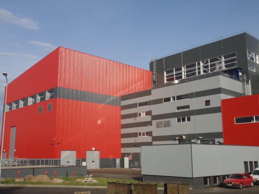
Figure 1 – Siauliai CHP biofuel-fired power unit
The biofuel-fired power unit was put into operation in 2012.
The Siauliai CHP biofuel-fired power unit consists of the following main components:
– system for receiving, sorting and feeding wood chips into boiler manufactured by Axis Industries (Lithuania);
– drum boiler DPCT 50-45-460 manufactured by DP Clean Tech Europe A/S (Denmark);
– ash and slag removal and flue gas cleaning system manufactured by Axis Industries (Lithuania) with two condensing economizers manufactured by Axis Industries under licence from SRE OPCON Group (Sweden) with a heat output of Q ≥ 4.9 MW;
– steam turbine MARK 2-H01 manufactured by МАN TURBO (Germany) with generator НТМ-110С04 manufactured by ELIN Motoren (Austria).
System for receiving, sorting and feeding wood chips into boiler manufactured by Axis Industries (Lithuania)
The biofuel is delivered by the covered dump trucks on weekdays with provision for creation of fuel stock for the biofuel-fired power unit operation on weekends or holidays. The trucks enter the territory, are weighed, registered, the moisture content is measured and the biofuel sample is taken. Then the trucks go to the fuel receiving facility, where there is a fuel receiving pit located below the storage floor level. The mechanized covered ground storage can hold a 5-day amount of biofuel for the biofuel-fired power unit operating at a nominal load. The storage is equipped with two grab cranes, which handle and evenly distribute the fuel at the storage or in the transfer fuel hopper. The grab cranes are controlled by the program, with regard to the sensors of boiler hopper fuel level and storage fuel level, and they also weigh fuel.
The fuel is supplied by three scraper conveyors, which are located in the hopper, to the belt conveyor, and then it is taken to the disk sorter. A metal separator is fitted above the belt conveyor, which takes the metal out of fuel into a separate container. The fuel that does not comply with the technical specifications is removed from the disk sorter into a separate container, then crushed or returned to the fuel supplier. The fuel suitable for combustion is taken from the sorter to the belt conveyor, then to the scraper conveyor feeding fuel into the boiler furnace hopper.
In order to increase the fuel supply reliability, the described fuel supply from the transfer hopper is duplicated.
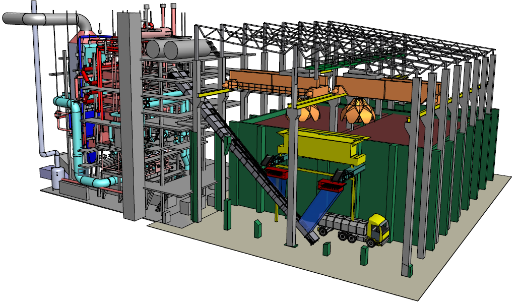
Figure 2 – System for receiving, sorting and feeding wood chips into boiler
Description of heat flow circuit
The CHP heat flow diagram is presented in Figure 3.
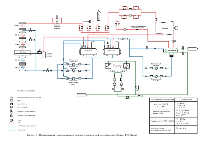
Figure 3 – Diagram of heat and power production by the Siauliai CHP biofuel-fired power unit
The feed water from the deaerator tanks is supplied with the feed water pumps, fitted with adjustable drives, into the boiler economizer.
The steam with a pressure of 45 bar and a temperature of 460 °С formed in the boiler moves to the steam turbine. In the event of emergency turbine stops and start-up modes, the circuit provides for the use of the start-up pressure-reducing and desuperheating station 45/0.3 bar (a) to discharge the steam from the boiler into the turbine condenser.
The steam from the turbine exhaust is supplied to the condenser, where the DH water is heated. The design heat load of the steam turbine condenser is 27.97 MW.
The condensate from the turbine condenser is supplied with the condensate pumps into the deaerators. The steam to the deaerators is supplied from the turbine regenerative extraction or through the pressure-reducing and desuperheating station 45/2.6 bar (a).
The heat produced at the CHP is delivered to the city through heating the DH water in the turbine condenser and contact economizers.
The DH water lines from the biofuel-fired power unit are connected to the circuit of the operating boiler house so that they operate jointly.
During the heating season, all return DH water comes to the DH pumps of the CHP, is heated in the contact economizer and steam turbine condenser. If necessary, the DH water is further heated by the boiler of the boiler house.
During the non-heating season and period between seasons, the whole supply of heat is provided from the biofuel-fired power unit.
Drum boiler DPCT 50-45-460 manufactured by DP Clean Tech Europe A/S (Denmark)
The purpose of boiler 50-45-460 is to produce superheated steam. This is a one-drum, vertical water tube, natural circulation boiler. The main design characteristics of the boiler are as follows:
boiler steam output …………………………................ 50 t/h;
superheated steam pressure ….…………………….…. 45 bar;
superheated steam temperature……..……………….... 460 оС;
feed water temperature ...…..………………………….. 104 оС;
exhaust gas temperature …………………………….… 150 оС;
boiler gross efficiency …………………...................…. 87 %;
steam output control range …………………………….. 42 – 100 %.
The fine particles of fuel are ignited when entering the combustion chamber, the larger particles are burnt on the grate. The particles burnt on the grate radiate heat and ignite the suspended particles. Depending on the fuel moisture and volatile matter content, about 75 % of energy is released during combustion of the suspended particles. When fresh fuel is fed on top of the burning fuel, it is dried up and quickly ignited.
The design fuel for the boiler plant is wood chips (sawdust, wood waste, bark) and wood chips/milled peat mixture in the proportion of 70/30 respectively.

Figure 4 – Arrangement of drum boiler
The characteristics of the wood fuel used in operation are presented in Table 1.
Table 1
Fuel characteristics | Design wood fuel | Allowable range of results variation |
Net calorific value, as received, MJ/kg | 7.6 | 5.2*- 12.3 |
Moisture content, average, % | 50 | 30 - 60 |
Ash content, dry (815), % | 3.0 | 0.2 - 4.0 |
Ash content, as received, % | 1.5 | - |
This boiler is a fully welded, water tube, natural water circulation boiler, permanently installed with a self-supporting structure, where the downcomers are part of the boiler supporting structure.
The boiler is of a U-shaped closed arrangement and consists of a combustion chamber and a convection pass connected at the top by a horizontal turning flue gas duct.
The walls of the boiler, convection pass and a vibrating grate compose an evaporation circuit of the boiler and form a fully welded gas-tight chamber for fuel combustion and hot flue gas removal.
The boiler has three circuits:
– first circuit consists of a furnace – radiation heating surfaces;
– second circuit consists of the radiation and convection heating surfaces with a superheater and an evaporator;
– third circuit consists of a water economizer and an air heater installed in a free-standing pass.
The vibrating grate is one of the boiler recirculation circuits.
The combustion chamber is an uptake flue gas duct divided into the combustion chamber and the boiler radiation heating surfaces. The upper part of the furnace is covered with a refractory lining. The lower part contains a vibrating grate and a slag removal channel.
The boiler convection pass is a downtake flue gas duct. The ceiling, front, rear and side walls of the convection pass are water-walled with the gas-tight panels which are part of the boiler evaporation system.
In the boiler convection pass, along the flue gas flow the following are successively located:
– tertiary superheater;
– secondary superheater;
– primary superheater;
– evaporator.
The evaporator and superheaters are made of horizontal drainable tubes which are brought through the boiler rear wall, which has external gas-tight covering that can be easily replaced if necessary.
The boiler superheater is a single-flow, three-stage superheater (SH1, SH2, SH3). To reduce the superheated steam temperature after SH1 and SH2, the spray desuperheaters (feed water injection into steam flow) are installed between the superheaters.
The control of the boiler outlet superheated steam temperature is performed by a cascade control of steam temperature by means of feed water sprays into the desuperheaters between the superheaters.
After the desuperheater installed before the secondary superheater, there is steam extraction for sootblowers.
The evaporator is installed in the convection pass after the superheater along the exhaust gas flow. The circulation circuit has its own closed cycle directly from the drum to the evaporator and back to the boiler drum.
The feed water supplied to the boiler drum is preliminarily heated by the exhaust gases in the water economizer located in a free-standing casing. The economizer is conditionally divided into two sections (stages). Some feed water flow goes via the primary economizer bypass line through the air heater and back into the feed water flow to the secondary water economizer to heat the combustion air, before LUFO.
The purpose of the LUFO air heater is to heat the primary air to above the fuel pyrolysis temperature. The LUFO air heater is conditionally divided into four sections. The air flows from the bundle to the bundle in counter flow to the flue gas.
The sootblowers are located between the tube bundles of superheaters, stages of water economizer and sections of air heater in order to remove soot from the heating surfaces.
Condensing steam turbine MARK 2-H01
The purpose of condensing steam turbine MARK 2-H01 with a capacity of 10.8 MW is to drive the alternating current generator НТМ 110СО04 manufactured by ELIN Motoren (Austria).
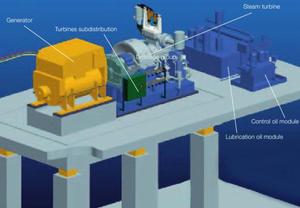
Figure 5 – Arrangement of turbine generator set
The turbine generator set consists of the following modules:
– steam turbine itself, which is a single-shaft unit and consists of the HP and LP cylinders;
– parallel shaft gearbox located between turbine and generator;
– three-phase synchronous generator with a brushless exciter.
The main design characteristics of the turbine at a nominal load are as follows:
live steam pressure………….................................... 42 bar (a);
live steam temperature….......................................... 455 °C;
condenser pressure…………..................................... 0.3 bar (a).
The steam from the boiler is supplied to the stop valve, and from there goes through the control valve to the LP cylinder. Having passed through the LP cylinder, the steam enters the condenser.
The purpose of the condenser is to condense the incoming steam, create the underpressure in the turbine exhaust nozzle, and create the condensate storage.
The demineralized water is delivered to the condenser (for filling). The air is pumped out of the turbine condenser by one steam-jet ejector, the second one is in standby. The condensate formed in the condenser is pumped out by one condensate pump (the second pump is in standby) and taken to the deaerator.
The main design characteristics of the condenser are as follows:
The main design characteristics of the condenser are as follows:
steam flow ………………………………………….… 45.970 t/h;
steam pressure ………………………………………… 0.3 bar (a);
condensation temperature …………………………..…. 70 оС;
heat transfer surface area …………………….……..…. 792 m2 .
The turbine has one uncontrolled extraction designed for heating and deaeration of water in the deaerators.
The turbine is equipped with a turning gear, which is designed to rotate the rotor in order to prevent it from bowing during the turbine warming up and cooling down and provides for the rotor speed of 300 rpm.
To seal the turbine rotor during operation in steady-state modes and in start-up and stop modes, the own steam is used.
The main design characteristics of generator DEV55E16 are as follows:
nominal power ...…………………………………. 13450 kVA;
active power …………………………………….... 10760 kW;
frequency ……………………………………..…... 50 Hz;
nominal speed …………………………………….. 1500 rpm
Flue gas cleaning system and condensing economizers
Having passed through a process cycle, the exhaust gases are discharged from the upper part of the boiler convection pass, and pass the cleaning system – the electrostatic precipitator and contact economizers.
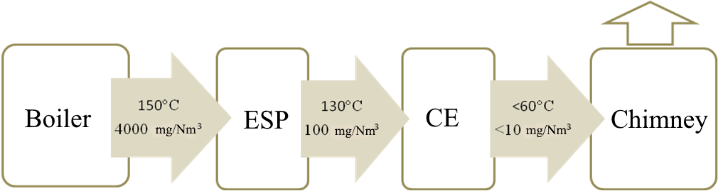
Figure 6 – Arrangement of flue gas cleaning system
The condensing economizers are designed to remove the solid particles from the exhaust gases and recover heat from the steam boiler exhaust gases. The operation principle of each condensing economizer is based on the reduction of exhaust gas temperature below the dew point and use of the latent heat of steam formation.
The main design characteristics of the contact economizer are as follows:
heat output …………………….……………. ≥ 4.9 MW;
flue gas temperature, inlet ………………….. 0÷200 оС;
solid particle concentration in flue gas ……... 0÷200 mg/m3;
CO concentration in flue gas ….…………..... 0÷3000 mg/m3;
NOx concentration in flue gas ……………… 0÷2000 mg/m3;
SO2 concentration in flue gas …….……….… 0÷1000 mg/m3;
DH water temperature ……………………..... 0÷70 оС;
DH water pressure …………………………... 6 bar.
The flap gates installed in the condensing economizers installation room are used to connect each individual condensing economizer to the process cycle or disconnect it, bypass the exhaust gases past the economizer directly into the chimney.
While passing through the inclined flue gas duct of the condensing economizer, the exhaust gases come in contact with the water droplets and are partially condensed (Fig. 7).
Having passed through the condensing economizer, the exhaust gases go into the chimney. An additional flue gas fan with a variable frequency drive is used to overcome the resistance of the sprayed water flows in each condensing economizer.
The water is supplied into the inclined flue gas duct of the condensing economizer by means of the special spray nozzles located along the flue gas duct. The particles of water serve as a direct (contact) heat exchanger by condensing the exhaust gas moisture and performing an additional function of filtering the solid particles remaining after the electrostatic precipitator. The condensate formed in the flue gas ducts together with the sprayed water flows down the inclined surface of the flue gas duct into the condensate tanks, and then is supplied by the condensate pump into the heat exchangers and heats the return DH water.
Thus, the exhaust gas latent heat enters the heat cycle of the biofuel-fired power unit.
Having passed through the heat exchangers and transferred its heat to the DH water, the condensate is supplied to the sprayers and thus completes the process cycle.
Some water after the heat exchanger is taken to the condensate polishing system VBH. Having passed through the polishing system, the water returns to the first tank.
The automatic pH level maintaining system measures and sets the required pH level of condensate flow in the first tank.
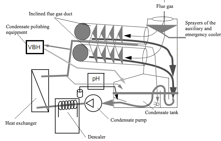
Figure 7 – Arrangement of condensing economizer
The return DH water comes to the DH pumps of the CHP, is heated in the contact economizer and steam turbine condenser. During the non-heating season, the whole supply of heat is provided from the biofuel-fired power unit.
To confirm the guaranteed performance of the biofuel-fired power unit stated by the Main Contractor in the course of a tender conducted by АВ “Siauliu Energija”, the heat supplier in the city of Siauliai, regarding a turnkey delivery of a biofuel-fired power unit, the performance tests were carried out when burning the design types of fuel.
The guarantee tests were carried out by our specialists jointly with the representatives of the Employer АВ “Siauliu Energija”, Main Contractor UAB “AXIS ТECHNOLOGIES” and suppliers of the main equipment.
The measurements and calculations were done according to the standards valid in the European Union and the Republic of Lithuania and applicable to this power-generating facility: SFS-EN 12952-15, DIN 1943, LAND 43-2001, SFS-EN 13284-1. The main values of the CHP performance were determined: generated electric power, generated thermal power of the biofuel-fired power unit, biofuel heat input into the boiler furnace, environmental performance of the power unit (concentration of nitrogen oxides (NOх), carbon monoxide (CO), solid ash particles in exhaust gas).
During the tests conducted in November-December 2012, the wood chips with the following average characteristics were burnt in the boiler furnace: calorific value of 9440 kJ/kg, moisture content (ar) of 43.5 %, ash content (ar) of 1.77 %. As a result of the tests, the guaranteed performance of the biofuel-fired power unit when burning the stated guaranteed fuel were confirmed.
In the whole range of operating loads, the electric power generated by the biofuel-fired power unit when burning 100 % of wood fuel exceeds the CHP design power threshold guaranteed by the equipment supplier.
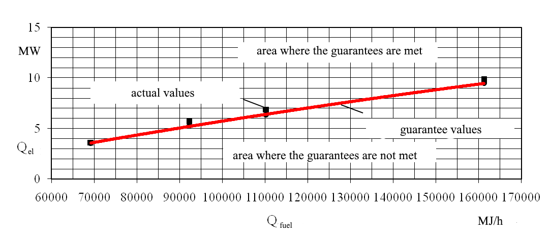
Figure 8 – Dependence of the electric power generated by the CHP, excluding the auxiliaries, on the fuel heat input when burning 100 % of wood fuel
The thermal energy is also in the area where the guaranteed thermal loads stated during the CHP construction are met. The dependence of the thermal energy generated by the Siauliai CHP biofuel-fired power unit on the fuel heat input into the boiler furnace is presented in Figure 9.
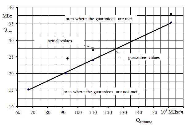
Figure 9 - Dependence of the actual performance of the CHP on the fuel heat inut when burning 100% of wood fuel.
The comparison of the actual performance of the biofuel-fired power unit corrected for the guaranteed fuel heat input with the performance guaranteed by the Main Contractor is presented in Tables 1 and 2.
Table 2 – Comparison of the actual performance of the biofuel-fired power unit with the performance guaranteed by the Main Contractor
Guaranteed thermal power of the CHP, MW | Guaranteed fuel heat input, MJ/h | Thermal power generated by the CHP corrected for the guaranteed fuel heat input, MW | Is the guaranteed heat generation met? Yes/No | Guaranteed electric power of the CHP, kW | Electric power generated by the CHP corrected for the guaranteed fuel heat input, kW | Is the guaranteed electricity generation met? Yes/No |
34.146 | 161283 | 37.629 | Yes | 9477 | 10311 | Yes |
24.000 | 114884 | 27.223 | Yes | 6752 | 7391 | Yes |
20.000 | 96230 | 21.845 | Yes | 5656 | 6282 | Yes |
15.000 | 72124 | 16.369 | Yes | 3892 | 4155 | Yes |
The main characteristics of the Siauliai CHP biofuel-fired power unit performance, i.e. the generated electric and thermal power, corrected for the design fuel heat input into the boiler furnace, exceed the guaranteed values in the whole range of operating loads.
The environmental performance of the biofuel-fired power unit does not exceed the guaranteed values adopted in the European Union:
– concentration of nitrogen oxides NOх in exhaust gas is 100.4-226 mg/m3, the guaranteed value being ≤ 600 mg/m3;
– concentration of carbon monoxide CO in exhaust gas is 60-620.4 mg/m3, the guaranteed value being ≤ 800 mg/m3;
– concentration of solid ash particles after electrostatic precipitator is 44.2-98.3 mg/m3, the guaranteed value being ≤ 200 mg/m3.
The determined actual performance of the Siauliai CHP biofuel-fired power unit exceeds the values stated by the Main Contractor.
Conclusions:
1 The biofuel-fired power unit in the city of Siauliai with superior performance is a real indicator of a possibility to abandon the expensive natural gas and change to the combustion of the renewable and cheap energy source.
2 The biofuel-fired power unit demonstrates high technical and environmental performance, which exceeds the guaranteed values in the whole range of operating loads.