
 Engineering services
 EXPERIENCE WITH WOOD FUEL COMBUSTION AT ALYTUS CHP BIOFUEL-FIRED POWER UNIT (REPUBLIC OF LITHUANIA)
To provide the city of Alytus with heat and electricity, the biofuel-fired CHP (Fig. 1) was put into operation, where the wood waste available in sufficient amount is used as a fuel. The dismantled hot water boiler PTVM-100 of the district boiler house was replaced with a 5.4 MW biofuel-fired power unit, the equipment for which was supplied by Axis Technologies.
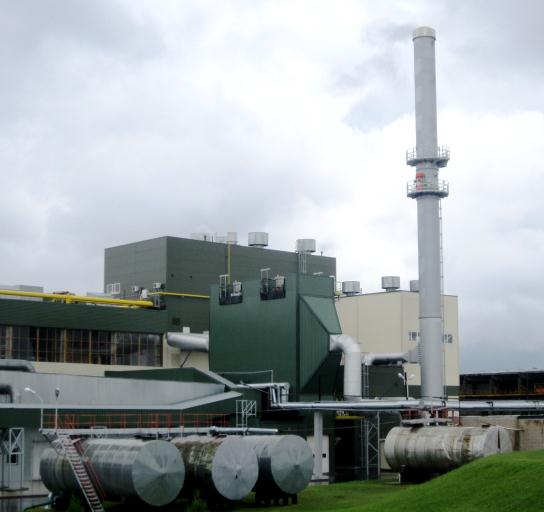
Figure 1 – General view of Alytus CHP put into operation in 2012
The biofuel-fired power unit consists of:
– steam boiler BFB 25-45-460 manufactured by RENEWA (Finland) (Dо = 25 t/h, Po = 4.5 MPa, to = 460 °С, t pr.a. = 104-130 оС, texh. = 160 оС, efficiency = 88 %);
– steam turbine MARK 2-H01 manufactured by МАN TURBO (Germany) with a backpressure (Q = 13,9 MW, p1//p2 = 42,0/0,3 bar (f), Ne = 5,4 MW), intended to drive the alternating current generator НТМ-171Е04 manufactured by ELIN Motoren (Austria);
– condensing economizer manufactured by SRE OPCON Group (Sweden) with a heat output of Q ≥ 4,9 MW.
Boiler BFB 25-45-460 is a single-drum, vertical water tube, natural water circulation boiler of a Ո-shaped arrangement, intended for wood fuel combustion in a fluidized bed (Fig. 2). The boiler is designed to burn 100 % of wood and up to 10 % of wood waste (bark, sawdust) or 10 % of straw. The fuel moisture content is up to 50-60 % of the total mass.

Figure 2 – Boiler BFB 25-45-460
The fuel is delivered by trucks to the mechanized ground storage, which can hold a three-day amount of biofuel for the boiler operating at a nominal load. The fuel supply system ensures a constant and controlled supply of fuel into the furnace combustion chamber. The operation of the storage mechanisms is controlled by the automation system. The fuel is supplied with a conveyor from the fuel storage though the crushers, metal separator, belt weigher to the fuel hopper. To push the fuel though, a self-propelled front-end loader with a 3.0 m³ bucket is provided at the storage.
When operating the biofuel-fired power unit, the fuel (wood chips) with the following characteristics is used: moisture content Wр = 40-60 %, ash content ≤ 7 %, operating net calorific value Qрн ≥ 5000 kW·h/t.
The fuel is burnt in the lower part of the furnace in the combustion chamber in a fluidized bed while operating at a balanced draft. The furnace lower part consists of the waterwall tubes, where the air nozzles are installed. The fluidized bed consists of 0.5-1.2 mm sand fraction, the bed thickness is 300-600 mm. The primary air is taken from the top of the boiler room and supplied by the primary air forced draft fan to the distribution trough, and then through the special nozzles into the combustion chamber. The nozzles are covered with a bed of sand and fuel. When the primary air is supplied through the nozzles, the bed “boiling”, the so-called fluidization, occurs. The air flow loosens the sand bed and forms an air/sand slurry. The boiler waterwalls are covered with a gunning refractory in the area of the fluidized bed.
The boiler lighting-up and solid fuel ignition are done with a fixed gas-fired burner on the furnace side wall; the fluidized bed is heated up during the boiler lighting-up. The sand temperature reaches the fire temperature of the wood, i.e. about 350-400 °C, the system of fuel supply to furnace is started. When the fuel begins to burn and the sand temperature reaches the normal operating temperature of 750-850 °C, the start-up gas-fired burner is switched off. During operation, the fluidized bed temperature is controlled with the secondary and tertiary air flows. If a drier fuel is burnt, the fluidized bed temperature may rise (up to 1000 °C). To avoid the temperature increase and the agglomeration of sand, there is an air recirculation into the primary air flow.
Where necessary (for example, wet fuel), to maintain the sand bed temperature which has dropped below 650 °C, you can use a gas-fired burner but limit its capacity to 4.2 MW (i.e. 60% of the load). When the sand bed temperature reaches 670-680 °C, the gas-fired burner is automatically switched off.
The thickness of the fluidized bed is controlled with regard to the bed aerodynamic resistance level, and the required amount of sand is added or discharged.
There is a neck from the rear wall panel at the top of the boiler combustion chamber. The combustion chamber, the ceiling, front, rear and side walls of the convection pass are water-walled with the gas-tight panels which are part of the boiler evaporation system. The inlet stage of the economizer and the tubular air heater “LUVO” are located in a free-standing column.
The secondary air is divided into two flows: one is fed into the combustion chamber through the nozzles located on the side walls of the furnace in a single tier (7 nozzles on each wall), and the other flow is fed into the combustion chamber through the nozzles located on the side walls above the lower tier nozzles (8 nozzles on each wall). The tertiary air flow is taken from the secondary air fan discharge and supplied into the combustion chamber through the nozzles located on the front and rear walls in a single tier (8 nozzles on each wall).
A flue gas recirculation circuit is provided to reduce the temperature in the combustion chamber and protect the fluidized bed against the unallowable temperature increase.
The combustion residues from the boiler and the replaced part of the fluidized bed sand are taken to the ash container.
After the power plant had been put into operation in 2012, the tests were carried out to determine its actual performance and check whether it was in compliance with the values stated by the Main Contractor. The specialists of our company and the representatives of the Employer “LITESKO” participated in testing. The tests lasted for 2 hours at a nominal load, with a time delay of at least 2 hours to stabilize the mode. During the tests, the wood chips with the following characteristics were burnt in the boiler furnace: calorific value Qрн = 9608 kJ/kg; moisture content (ar) Wр = 42.5 %; ash content (ar) Ар = 2.76 %.
During the tests, the boiler steam output was 26.4 t/h, superheated steam temperature, 450 оС, exhaust gas temperature after boiler, 172 оС, flue gas temperature at the system outlet, after contact economizer, 44.7-44.9 оС. The deviations of the values did not exceed the allowable ones. The exhaust gas NOх content was 286 mg/m3, СO content, 222 mg/m3, and ash particle concentration after electrostatic precipitator, 4,84 mg/m3, which was much less than the guaranteed values. According to the test results, the biofuel-fired power unit boiler efficiency when burning the wood chips was 88.08 %.
Conclusions:
A method of wood fuel combustion using the fluidized bed technology in boiler BFB 25-45-460 manufactured by RENEWA (Finland) has a prospect to be further implemented, because it shows high technical and environmental performance, and is an alternative to the use of natural gas.